15
Maxim Integrated
MAX19792
500MHz to 4000MHz Dual Analog Voltage Variable
Attenuator with On-Chip 10-Bit SPI-Controlled DAC
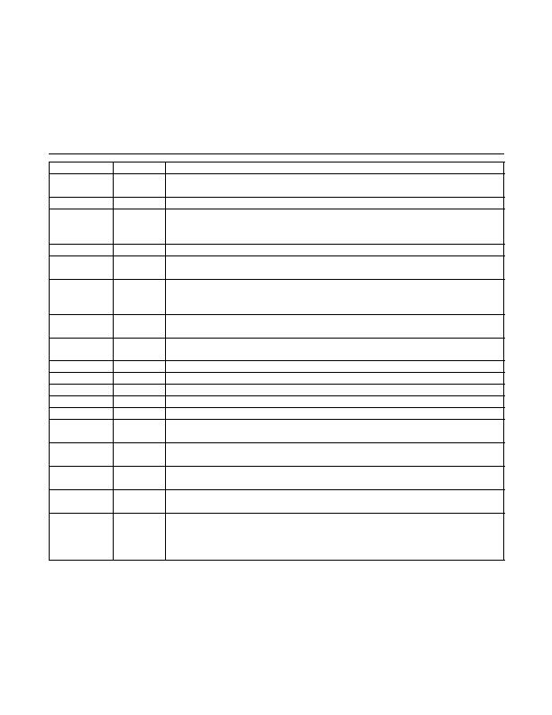
Pin Description (continued)
PIN
NAME
DESCRIPTION
13
V
CC
Analog Supply Voltage. Bypass to GND with a capacitor as close as possible to the device. See
the Typical Application Circuit.
14
REF_IN
DAC Reference Voltage Input (Optional)
15
REF_SEL
DAC Reference Voltage Selection Logic Input
Logic = 0 to enable on-chip DAC reference.
Logic = 1 to use off-chip DAC reference (pin 14).
16
DAC_LOGIC DAC Logic Control Input (Table 1)
17
COMP_OUT
Comparator Logic Output. Use a 4.7pF capacitor to reduce any potential rise-time glitching
when the comparator changes state.
18
MODE
Attenuator Control Mode Logic Input
Logic = 1 to enable attenuator step control.
Logic = 0 to enable attenuator SPI control.
19
DWN
Down Pulse Input
Logic pulse = 0 for each step-down.
20
UP
Up Pulse Input
Logic pulse = 0 for each step-up.
19/20
DWN/UP
Logic = 0 to both pins to reset the attenuator to a minimum attenuation state
21
CLK
SPI Clock Input
22
DIN
SPI Data Input
23
DOUT
SPI Data Output
24
CS
SPI Chip-Select Input
25
V
CC
Digital Supply Voltage. Bypass to GND with a capacitor as close as possible to the device.
See the Typical Application Circuit.
29
OUT_B
Attenuator B RF Output. Internally matched to 50I over the operating frequency band. This pin,
if used, requires a DC block. If this attenuator is not used, the pin can be left unconnected.
32
V
CC
Attenuator B Power Supply. Bypass to GND with a capacitor and resistor, as shown in the
Typical Application Circuit.
35
IN_B
Attenuator B RF Input. Internally matched to 50I over the operating frequency band. This pin,
if used, requires a DC block. If this attenuator is not used, the pin can be left unconnected.
EP
Exposed Pad. Internally connected to GND. Solder this exposed pad to a PCB pad that uses
multiple ground vias to provide heat transfer out of the device into the PCB ground planes.
These multiple via grounds are also required to achieve the noted RF performance. See the
Layout Considerations section.
发布紧急采购,3分钟左右您将得到回复。
相关PDF资料
MAX19794ETX+
ATTENUATR 46DB 50OHM 4GHZ 36TQFN
MAX2365ETM+T
IC TRANSMITTER QUAD 48TQFN-EP
MAX2369EGM+TD
IC TRANSMITTER QUAD 48QFN-EP
MAX2850ITK+
TRANSMITTER MIMO 5GHZ 4CH 68TQFN
MAX7057ASE+T
IC TRANSMITTER ASK/FSK 16-SOIC
MBA-2060
ANTENNA METROLOGY BICONICAL
MC33493ADTBER2
IC RF TRANSMITTER UHF 14-TSSOP
MDEV-916-ES
KIT MASTER DEVELOP 916MHZ ES SRS
相关代理商/技术参数
MAX19792ETX+T
功能描述:衰减器 -IC 500MHz to 3000MHz Attenuator RoHS:否 制造商:Skyworks Solutions, Inc. 最大衰减:18 dB 容差: 阻抗: 功率额定值:30 dBm 安装风格:SMD/SMT 工作温度范围:- 40 C to + 85 C
MAX19793ETX+
功能描述:衰减器 -IC 2000MHz to 5000MHz Attenuator RoHS:否 制造商:Skyworks Solutions, Inc. 最大衰减:18 dB 容差: 阻抗: 功率额定值:30 dBm 安装风格:SMD/SMT 工作温度范围:- 40 C to + 85 C
MAX19793ETX+T
功能描述:衰减器 -IC 2000MHz to 5000MHz Attenuator
RoHS:否 制造商:Skyworks Solutions, Inc. 最大衰减:18 dB 容差: 阻抗: 功率额定值:30 dBm 安装风格:SMD/SMT 工作温度范围:- 40 C to + 85 C
MAX19794ETX+
功能描述:衰减器 -IC 10MHz to 500MHz Attenuator RoHS:否 制造商:Skyworks Solutions, Inc. 最大衰减:18 dB 容差: 阻抗: 功率额定值:30 dBm 安装风格:SMD/SMT 工作温度范围:- 40 C to + 85 C
MAX19794ETX+T
功能描述:衰减器 -IC 10MHz to 500MHz Attenuator RoHS:否 制造商:Skyworks Solutions, Inc. 最大衰减:18 dB 容差: 阻抗: 功率额定值:30 dBm 安装风格:SMD/SMT 工作温度范围:- 40 C to + 85 C
MAX1979ETM
功能描述:电压模式 PWM 控制器 RoHS:否 制造商:Texas Instruments 输出端数量:1 拓扑结构:Buck 输出电压:34 V 输出电流: 开关频率: 工作电源电压:4.5 V to 5.5 V 电源电流:600 uA 最大工作温度:+ 125 C 最小工作温度:- 40 C 封装 / 箱体:WSON-8 封装:Reel
MAX1979ETM+
功能描述:电压模式 PWM 控制器 Integrated Temp Ctlr for Peltier Modules RoHS:否 制造商:Texas Instruments 输出端数量:1 拓扑结构:Buck 输出电压:34 V 输出电流: 开关频率: 工作电源电压:4.5 V to 5.5 V 电源电流:600 uA 最大工作温度:+ 125 C 最小工作温度:- 40 C 封装 / 箱体:WSON-8 封装:Reel
MAX1979ETM+T
功能描述:电压模式 PWM 控制器 Integrated Temp Ctlr for Peltier Modules RoHS:否 制造商:Texas Instruments 输出端数量:1 拓扑结构:Buck 输出电压:34 V 输出电流: 开关频率: 工作电源电压:4.5 V to 5.5 V 电源电流:600 uA 最大工作温度:+ 125 C 最小工作温度:- 40 C 封装 / 箱体:WSON-8 封装:Reel